As The Oil Drum turns into an archival site only, Bob Tregilus of This Week in Energy dropped a note to see if I would appear on the show and respond to a few questions that included both that topic and some chat about the Bakken, inter alia.
I was very glad to oblige, and the show has just been posted at "This Week in Energy."
I hope you find it of interest.
Saturday, August 31, 2013
The end of the rowing sagas
Earlier this month I had noted that there were a couple of boats trying to row/sail down the Northwest Passage. It turns out that my awareness of the number was off by a number of boats - there were several others that I was not aware of.
However the ice came early and with darkness approaching, and the days and nights getting colder, both the two that I was following - the Arctic Joule and the Fairmont's Passion ended their attempts at Cambridge Bay. In both cases this was about half-way along their intended route, but among other things early encounters with ice slowed their progress, and they both called it quits yesterday - coincidently arriving at Cambridge Bay within hours of one another.
Sail World notes that there is 60% more ice in the Arctic this year than there was at this time last year, and that both ends of the Northwest Passage are, therefore, already blocked trapping those trying to make it through.

Figure 1. Locations along the Northwest Passage.
I have taken the Sail World map and added the position of Cambridge Bay and the two target end points for the ventures. The Arctic Joule was heading for Pond Inlet, while Fairmont's Passion was aiming for Resolute Bay. I suspect that news stories commenting on this indication that the Arctic is clearly not ice free will be somewhat sparse. And few will note that the Inuit made it a thousand years ago, establishing the Thule colony in Greenland from their origins in Alaska.
There is really nothing else to say.
Read more!
Wednesday, August 28, 2013
Waterjetting 12d - The heat of a waterjet cut
In the last three posts I have been discussing the quantity of heat that is created when machine tools are used in the cutting of rock, metals and other materials. The amount that the temperature of both the cutting tool and work piece material will increase, and the effect that this has on the cutting tool and the finished part can, as I have shown, be reduced if a quite small stream of high-pressure water is directed into the small zone where the cutting is taking place.
But what happens if the cutting process doesn’t use the large scale typical mechanical cutting tools, but instead uses the very small particles embedded within the jet stream itself as part of an abrasive waterjet cutting system? For many years the evidence, after the cut was over, indicated that there was very little heat build-up in the part, and the process appeared to be a “cold cut,” but there was no immediate evidence, because of the rapidity with which the cut was made. However, with advances in technology that limitation was removed, and research scientists at the University of Hannover have now been able to make temperature measurements during cutting. (A Thermographical Map of Tool and Workpiece During the Cutting Process by Plain Waterjet and Abrasive Waterjet up to 900 MPa, H. Louis, A. Schenk, F. Pude and M. Mohamed, 17th International Conference on Waterjet Cutting Technology).
The group used an infra-red camera connected into a computer to capture images as an abrasive waterjet cut into a target work sample. The instrument had been calibrated to show the color temperatures that the image revealed.

Figure 1. Temperatures read through an infrared camera as an abrasive jet cuts into a target plate. (H. Louis et al, ibid)
The arrangement by which the images were obtained was relatively simple:

Figure 2. Experimental arrangement allowing capture of the temperature build-up in the cutting head, the abrasive jet and the work piece during an AWJ cut (H. Louis et al, ibid).
During the course of the experiment the size of the cutting jet and the pressure were changed to find how these controlled the temperatures that were generated in the different parts of the operation. The work first examined the results when only a plain waterjet, without abrasive particles, was used in cutting.

Figure 3. Temperature build-up when plain waterjets (at 125,000 psi) are being used to cut a piece. (H. Louis et al, ibid)
Note that there is not a large amount of heat generated in the part, in this case a temperature rise to 126 Deg F was measured, though the temperature rise in the nozzle holder was similar in range. When the effects of jet flow and pressure were plotted, the role that an increase in pressure played in raising the part temperature around the cutting zone is clear. Note, in Figure 3, the region over which the temperature has been raised in the work piece.
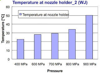
Figure 4. Temperature rise in the nozzle holder as a function of jet pressure. (H. Louis et al, ibid)
Note that at pressures of up to 100,000 psi (700 MPa) the temperature rise is only up to 86 deg F, much less than that in conventional mechanical cutting.
When abrasive is added to the jet stream, then the temperatures generated, as Figure 1 indicated, are higher in the nozzle holder, because of the impact of the particles with the focusing tube as part of the particle acceleration. The piece was moved under the jet at 1.2 inches/minute, with an abrasive feed of 0.06 lb/minute, with jet pressures varied from 42,000 psi to 115,000 psi. (300 to 800 MPa). The target was a metal alloy.
Not surprisingly as the pressure in the jet increased, so did the temperature in the focusing tube.

Figure 5. Temperature increase in the focusing tube, as a function of jet pressure (H. Louis et al, ibid).
Temperatures were measured at the top, middle and bottom of the cut which the AWJ made through the target material, and these are shown in the following plot:

Figure 6. Temperature build-up in the work piece during the cutting operation (H. Louis et al, ibid).
The graph shows that the temperature build-up is greatest in the middle of the cut, although this difference is small, and begins to disappear as the jet pressure increases. At 100,000 psi the temperature can rise to 150 deg F.
In most cutting work that temperature rise would not be enough to cause any damage to the part being cut. Where very temperature sensitive materials have been cut with the jet at lower pressures and higher speeds at MS&T the zone of influence of the cutting operation was measured in microns.
It is in living tissue, which can be more sensitive to temperature, where this can be a problem. The University in Hannover is internationally recognized for the work that it has been carrying out in to the use of high pressure waterjets in medical applications. While this is a subject for another day (or several since the range of applications continues to grow from year to year) the caution comes from work on cutting bone and reported at the 18th International Jet Cutting Conference in Gdansk by Biskup et al “Temperature measurement during abrasive water jet cutting of cortical bone measured by thermocouples”). Bear in mind, however, that one of the problems that the technology is seeking to address in these bone cutting experiments is to achieve a better quality cut than can be achieved with a hand saw, which has often been the tool used by a surgeon when dissecting bone, and the required edge quality is sometimes more difficult to achieve with that tool.

Figure 7. Temperature build-up in bone under varying conditions and for two bone thicknesses, as a function of residence time. (Biskup et al, ibid)
It can be seen that a thicker bone sample does become vulnerable to too high a temperature if there is a significant exposure time before the part is pierced. However, with an appropriate selection of parameters the temperature can be kept down in a range where the tissue does not die, and the considerable advantages to jet use can therefore be used.
Keeping the parts being cut cool is important in very delicate and precise work, where thermal distortion of the metal, particularly in thin but deep cuts, can otherwise lead to unacceptable failures to maintain tolerance.
Read more!
Monday, August 26, 2013
Tech Talk - A Dickensian Situation revisited
Back in March 2005 I posted my first offering to the new site that Kyle and I had agreed to call “The Oil Drum.” Now, some eight years later, this will be my final Tech Talk to appear on that site, and it is perhaps appropriate to go back to that first post, and make a couple of comments on how it panned out. It read as follows:

Figure 1. Changes in liquid supply sources from 2000 to 2040 as anticipated by Exxon Mobil, with lines added to show 2005 and 2013. (The Outlook for Energy: A view to 2040)
I have added lines to show the situation in 2005, when the piece was written, and for this year. It is worth noting that, using the definitions that Exxon Mobil give, conventional crude and condensate production has, indeed, declined since I wrote those words. And if one includes Oil Sand and Deepwater then production has remained fairly stable at the levels back in 2005, and will (according to EM) likely stay so into the projected future.
The three sources that I had underestimated, in terms of production growth were in Biofuels (which is now at around 2 mbd), the growth in Natural Gas Liquids (which for OPEC alone is now projected to reach 6 mbd by next year up from around 3 mbd in 2005, and the growth in tight oil. This latter development, particularly with the use of long horizontal wells that are artificially fractured and injected with a slick-water suspension of a proppant, has been very successful in developing resources which were otherwise at best marginally economic. However the relative contribution that this is expected to make in overall supply is not that great, and I expect that, because of the high decline rates in individual wells, that this will only contribute on the margin of the problem.
When I began writing at The Oil Drum I was concerned that there was a lack of understanding of the impact that reservoir decline rates would have on long-term supply. As larger fields are depleted, so the world turns to smaller fields and these drain more rapidly, so that more and more are needed. (The Red Queen situation that Rune Likvern and others have so aptly described.
Deepwater resources have proven to be more difficult to bring on line than originally estimated and thus, for example, in the case of Brazil OPEC now anticipates that the production from the Lula field (originally Tupi) will only offset declines from wells in the rest of the country, with perhaps only a gain of 10 kbd overall from the addition of the 100 kbd expected from wells now coming on line. And thus, while this is a resource getting more attention (there are expected to be 60 Deepwater rigs in the Gulf of Mexico by 2015) the slow pace of development may not fill the increasing gap left as conventional oil production continues to fall, as Exxon Mobil suggest.
In retrospect, therefore, I was wrong in anticipating a relatively immediate impact from an anticipated imbalance between oil supply and demand. But, within the time frame the price of oil has risen, and the future looks no happier than it did back in 2005. The threats have changed – we seem to be in a quiescent period for major Gulf Hurricanes, for e.g. – but the threat of growing and spreading turmoil in MENA makes it less certain that we can count on much increase in production from Iraq, among others. Russian production rebounded more than I expected, but whether that can be sustained is still in doubt. The hope, at the beginning, was that the threat would spur increased looks into alternate sources of liquid fuel. But while there was a flurry of activity into biofuels (and I myself saw algal work that held a great potential, - though funding has now disappeared for that effort) there is less of a feeling of urgency in the air. Wind and solar sources have reached a point where they are no longer novel, and there is not much else in the near term that holds much potential.
Oil production takes money and resources, but most critically it takes time. Without that investment, particularly in viable alternatives, the oil “income” (supply) will likely soon start to fall short of the oil “expenses” (demand) and as Mr. Micawber so aptly said “we are forever floored.”
When these posts began, technical blogs, such as TOD, posed the potential for mass education in a way that had not been seen before. Readers have been kind in regard to the quality of the posts themselves. But the contributions from those interested, and those in industry who took the time to comment and debate ended up making this much stronger than the initial words in any post. Expertise came in many forms and informed me as well as the rest of the readers in what turned into a wonderful opportunity for many people to understand some of the complexities of supplying the world with hydrocarbon energy. I was thus able to help bring a little understanding of the energy business to vastly more folk than I had in the entirety of my academic career.
I will always be grateful to Kyle for giving me the opportunity to make this contribution, and to his efforts which led to its great success. I can illustrate that with some numbers – as an academic I took persuasion to allow my class size to rise much above 20, and at Bit Tooth Energy I see about 300 readers on a typical good day – Kyle had us above that number in a very few months, and at its peak TOD was handling 200 times that number. The site would not have continued too long as it grew in size without the indefatigable SuperG, who kept the site up under wide ranging pressures, and took care of the technical side of the house. Leanan brought and kept us readers, and provided many of the topics that we needed to create the posts on site, and Gail kept me going with encouragement and support in more difficult times. Nate orchestrated the closing posts and that was not easy.
The folks Kyle brought in to build an international forum were formidable and highly productive, and so to them, and to all of the gentle readership I say again a heartfelt “Thank You!”
(Heading Out – Dave Summers in the mundane world – will continue to write Tech Talks at Bit Tooth Energy, though he writes on a wider range of topics at that site).
When I was young I was fascinated by a small china statuette that my Grandparents had of Mr Micawber. He is a character, and a sympathetic one, in Charles Dickens's book "David Copperfield", in the course of which he goes into debt, His explanation of his financial condition can be compared to the coming world experience as we now live through Hubbert's Peak. You might, in today's phraseology, call this the Money quote:
'My other piece of advice, Copperfield,' said Mr. Micawber, 'you know. Annual income twenty pounds, annual expenditure nineteen nineteen and six, result happiness. Annual income twenty pounds, annual expenditure twenty pounds ought and six, result misery. The blossom is blighted, the leaf is withered, the god of day goes down upon the dreary scene, and - and in short you are for ever floored. As I am!'.
In this case consider that our expenses, i.e. the world use of oil, went up last year to around 83 million barrels every day (mbd). (A barrel is 42 gallons). Now as long as our supplies (income) can match this outlay then we are in happiness. This was, in relative terms, where we ended last year.
However this year our expenses are going to go up. It is a little difficult to predict exactly how much but current predictions are for this to be around 2 mbd. Let us equate this to the old English sixpence (which was back then worth about a dime. Twenty pounds being worth about $100).
If we follow the Micawber example if our income, world oil supply is equal to or greater than our expenses then we can stay happy. But here is the rub.
When world oil production is just about as high as it can be (non-OPEC countries are now producing just about as fast as they can) and OPEC spare capacity is down to around an additional 1.3 mbd. then our income this year will likely not be much above 85 mbd, if it gets there. (In a later post I will explain why it probably won't).
So we are at the point where within the next few months income and expenditures will be in balance (Micawber's twenty pounds). Except that the industry being a big one there are always things going wrong. In the latter part of last year for example we had:
• the hurricanes in the Gulf that closed down about 0.5 mbd of production for several months,
• oil production in Iraq, which should be around 3 mbd, but because of pipeline bombings etc dropped below 2 mbd,
• there were frequent threatened strikes on the oil platforms in Nigeria,
• and Russian production declined more drastically than had been anticipated.
Some of these are still with us, some have been resolved. And other problems, such as the complete employment of the world tanker fleet, have yet to make an impact. But any one can drop supply.Looking around it is reasonable to note that we don’t see the level of misery that, from reading that post, one might have expected to happen. We have gone through a major recession, yet demand has, overall, increased and production has risen to meet that demand. Yet looking at how this has been met is instructive.
Yet while our supply (income) is about at a peak (twenty pounds), our expenses (demand) are still going up by this sixpence a year. So that some time this year expenses will have gone from twenty pounds to twenty pounds and sixpence. A number of economists had been predicting that there would be a reduction in the rise in demand to keep us below that figure, but it is already clear that they do not adequately recognize the considerable needs in China and India that drive this increase (and they only have to read the papers to see it).
The big question is when will we reach the point that we cross over the balance point. Right now with the Saudi Arabian government saying that they can increase production by up to 1.5 mbd one might think we could get through to just about the end of this year. Unfortunately some of us are a little cynical about that number, and I'll explain why in another post.
One final gloomy thought - production in other countries (such as the UK) is falling, and the countries that used that supply must find another source. And if we are now at the peak of production, then our income cannot increase above twenty pounds and and may indeed fall back below twenty pounds, while our expenses will continue to increase to twenty pounds and sixpence. It is not the absolute size of the market that will now drive, but the relatively small fluctuations that take us out of balance.
The result is misery, and we are for ever floored.

Figure 1. Changes in liquid supply sources from 2000 to 2040 as anticipated by Exxon Mobil, with lines added to show 2005 and 2013. (The Outlook for Energy: A view to 2040)
I have added lines to show the situation in 2005, when the piece was written, and for this year. It is worth noting that, using the definitions that Exxon Mobil give, conventional crude and condensate production has, indeed, declined since I wrote those words. And if one includes Oil Sand and Deepwater then production has remained fairly stable at the levels back in 2005, and will (according to EM) likely stay so into the projected future.
The three sources that I had underestimated, in terms of production growth were in Biofuels (which is now at around 2 mbd), the growth in Natural Gas Liquids (which for OPEC alone is now projected to reach 6 mbd by next year up from around 3 mbd in 2005, and the growth in tight oil. This latter development, particularly with the use of long horizontal wells that are artificially fractured and injected with a slick-water suspension of a proppant, has been very successful in developing resources which were otherwise at best marginally economic. However the relative contribution that this is expected to make in overall supply is not that great, and I expect that, because of the high decline rates in individual wells, that this will only contribute on the margin of the problem.
When I began writing at The Oil Drum I was concerned that there was a lack of understanding of the impact that reservoir decline rates would have on long-term supply. As larger fields are depleted, so the world turns to smaller fields and these drain more rapidly, so that more and more are needed. (The Red Queen situation that Rune Likvern and others have so aptly described.
Deepwater resources have proven to be more difficult to bring on line than originally estimated and thus, for example, in the case of Brazil OPEC now anticipates that the production from the Lula field (originally Tupi) will only offset declines from wells in the rest of the country, with perhaps only a gain of 10 kbd overall from the addition of the 100 kbd expected from wells now coming on line. And thus, while this is a resource getting more attention (there are expected to be 60 Deepwater rigs in the Gulf of Mexico by 2015) the slow pace of development may not fill the increasing gap left as conventional oil production continues to fall, as Exxon Mobil suggest.
In retrospect, therefore, I was wrong in anticipating a relatively immediate impact from an anticipated imbalance between oil supply and demand. But, within the time frame the price of oil has risen, and the future looks no happier than it did back in 2005. The threats have changed – we seem to be in a quiescent period for major Gulf Hurricanes, for e.g. – but the threat of growing and spreading turmoil in MENA makes it less certain that we can count on much increase in production from Iraq, among others. Russian production rebounded more than I expected, but whether that can be sustained is still in doubt. The hope, at the beginning, was that the threat would spur increased looks into alternate sources of liquid fuel. But while there was a flurry of activity into biofuels (and I myself saw algal work that held a great potential, - though funding has now disappeared for that effort) there is less of a feeling of urgency in the air. Wind and solar sources have reached a point where they are no longer novel, and there is not much else in the near term that holds much potential.
Oil production takes money and resources, but most critically it takes time. Without that investment, particularly in viable alternatives, the oil “income” (supply) will likely soon start to fall short of the oil “expenses” (demand) and as Mr. Micawber so aptly said “we are forever floored.”
When these posts began, technical blogs, such as TOD, posed the potential for mass education in a way that had not been seen before. Readers have been kind in regard to the quality of the posts themselves. But the contributions from those interested, and those in industry who took the time to comment and debate ended up making this much stronger than the initial words in any post. Expertise came in many forms and informed me as well as the rest of the readers in what turned into a wonderful opportunity for many people to understand some of the complexities of supplying the world with hydrocarbon energy. I was thus able to help bring a little understanding of the energy business to vastly more folk than I had in the entirety of my academic career.
I will always be grateful to Kyle for giving me the opportunity to make this contribution, and to his efforts which led to its great success. I can illustrate that with some numbers – as an academic I took persuasion to allow my class size to rise much above 20, and at Bit Tooth Energy I see about 300 readers on a typical good day – Kyle had us above that number in a very few months, and at its peak TOD was handling 200 times that number. The site would not have continued too long as it grew in size without the indefatigable SuperG, who kept the site up under wide ranging pressures, and took care of the technical side of the house. Leanan brought and kept us readers, and provided many of the topics that we needed to create the posts on site, and Gail kept me going with encouragement and support in more difficult times. Nate orchestrated the closing posts and that was not easy.
The folks Kyle brought in to build an international forum were formidable and highly productive, and so to them, and to all of the gentle readership I say again a heartfelt “Thank You!”
(Heading Out – Dave Summers in the mundane world – will continue to write Tech Talks at Bit Tooth Energy, though he writes on a wider range of topics at that site).
Read more!
Tuesday, August 20, 2013
Waterjetting 12c - Jet assisted metal cutting
The first two posts in this section described how, in cutting through rock, the tool and the rock would be compressed together so that temperatures could be created in and around the tool that would exceed 2,000 deg C. That temperature is sufficient to melt the cutting tool, and in other situations is hot enough that it can ignite pockets of gas in underground operations that can have fatal results. However, by adding a small flow (less than 1 gpm) of water to the cutting pick not only is this risk of gas ignition or pick melting significantly diminished, but the water acts to remove the fragments of the rock as they are broken under the bit. This has two beneficial effects, first it removes the small rock that would otherwise be re-crushed and rub against the bit, causing the temperature rise due to friction. The second is that by also keeping the tool cool and sharp it can penetrate much deeper into the rock under the same forces, improving the efficiency of the cutting.
When a cutting tool is used to cut metal instead, the processes are somewhat different. However, because the tool rubs against the metal and cuts and deforms the metal that will be removed as a chip heat will still build up around the cutting zone.

Figure 1. Temperatures around a cutting tool in metal (Gear Solutions Magazine )
If you look closely at the temperature contours you will see that the lines stretch beyond the point where the cut is being made, and both the chip and the machined surface of the metal heat up to 500 degC. This narrow strip of metal on the surface of the piece is referred to as the Heat Affected Zone or HAZ, since the metal in this region has had its properties changed by the heat and deformation. And while the impact is more severe with a thermal method of cutting (such as plasma) there is some affect with mechanical cutting.
This can be seen, for example, if a metal piece is machined without cooling of the interface between the bit and the chip. Depending on the material being cut, this can lead to chips that are thermally damaged, are long and can be dangerously hot.

Figure 2. Strips of metal milled without cooling (Dr. Galecki)
If the surface of the chips are examined then the amount of heat damage is evident.

Figure 3. Surface of the chip showing the damage from the heat during cutting. (Dr. Galecki)
However this problem with the heat generated during cutting has been widely recognized, and so it has become standard practice to play a cooling fluid over the cutting zone during machining. To be effective the water must pass into the passage along the tool face and down into the cutting zone. It thus acts both to lubricate the passage of the chip up the blade, and separating it from the cutting tool, while cooling the bit and keeping it sharp.

Figure 4. Insertion of the jet into the cutting zone. (Dr. Mazurkiewicz)
When this is properly placed, and as with the jet assisted cutting of rock the precision required in placing the jet is around 1.10th of an inch, then the chip and metal surface are cooled and the tool remains sharp.
However, with conventional, lower pressure cooling, while the chip length is reduced and the surface is somewhat improved, overall cutting forces do not change.
 Figure 5. Chips formed with conventional cooling (note the poor edge quality). (Dr. Galecki)
When the waterjet pressure is increased to the ultra-high pressure range, so as to ensure that adequate water reaches the tool, then the cutting forces are reduced and the amount of damage to the metal is further reduced
The result can be seen in the form of the chips that are removed, which are now much shinier in appearance:

Figure 6. Chips from high-pressure jet assisted cutting (Dr. Galecki)
Note that the surface of the chips are shiny, and that they are relatively small in size. The shiny surface is similarly reflected in that left on the machined part.

Figure 7. Cut surface left after high-pressure jet assistance to the cutting tool.
The resulting reduction in damage to the machined surface, as well as the lower machine forces, and the consequent lowering of the potential for “chatter” during cutting gives a higher cut surface quality which, because of the reduced damage to the surface has a higher fatigue resistance.
The amount of modification required to the equipment is not necessarily large, since the high pressure water can be carried to the tool through relative small tubing that has a small footprint. The pump can be located elsewhere. Further, while conventional cooling requires additives to the water (which make it more costly to treat the scrap) the clean water used in the jet makes this less of a concern.

Figure 8. Arrangement with a jet added to the cutting tool on a lathe. There are also instruments on the platform. (Dr. Galecki)
These results show that the heat damage that can be anticipated with conventional machining of metal can be significantly reduced with the addition of high-pressure water. This becomes even more clear where abrasive is added to the jet stream, and fortunately, thanks to colleagues in Germany, we have thermal images of this, which I will share, next time.
(For further reading see Mazurkiewicz, M., Kabala, Z., And Chow, J., "Metal Machining With High Pressure Water Cooling Assistance - A New Possibility," ASME Journal of Engineering for Industry, Vol. 111, February, 1989.)
When a cutting tool is used to cut metal instead, the processes are somewhat different. However, because the tool rubs against the metal and cuts and deforms the metal that will be removed as a chip heat will still build up around the cutting zone.

Figure 1. Temperatures around a cutting tool in metal (Gear Solutions Magazine )
If you look closely at the temperature contours you will see that the lines stretch beyond the point where the cut is being made, and both the chip and the machined surface of the metal heat up to 500 degC. This narrow strip of metal on the surface of the piece is referred to as the Heat Affected Zone or HAZ, since the metal in this region has had its properties changed by the heat and deformation. And while the impact is more severe with a thermal method of cutting (such as plasma) there is some affect with mechanical cutting.
This can be seen, for example, if a metal piece is machined without cooling of the interface between the bit and the chip. Depending on the material being cut, this can lead to chips that are thermally damaged, are long and can be dangerously hot.

Figure 2. Strips of metal milled without cooling (Dr. Galecki)
If the surface of the chips are examined then the amount of heat damage is evident.

Figure 3. Surface of the chip showing the damage from the heat during cutting. (Dr. Galecki)
However this problem with the heat generated during cutting has been widely recognized, and so it has become standard practice to play a cooling fluid over the cutting zone during machining. To be effective the water must pass into the passage along the tool face and down into the cutting zone. It thus acts both to lubricate the passage of the chip up the blade, and separating it from the cutting tool, while cooling the bit and keeping it sharp.

Figure 4. Insertion of the jet into the cutting zone. (Dr. Mazurkiewicz)
When this is properly placed, and as with the jet assisted cutting of rock the precision required in placing the jet is around 1.10th of an inch, then the chip and metal surface are cooled and the tool remains sharp.
However, with conventional, lower pressure cooling, while the chip length is reduced and the surface is somewhat improved, overall cutting forces do not change.

When the waterjet pressure is increased to the ultra-high pressure range, so as to ensure that adequate water reaches the tool, then the cutting forces are reduced and the amount of damage to the metal is further reduced
The result can be seen in the form of the chips that are removed, which are now much shinier in appearance:

Figure 6. Chips from high-pressure jet assisted cutting (Dr. Galecki)
Note that the surface of the chips are shiny, and that they are relatively small in size. The shiny surface is similarly reflected in that left on the machined part.

Figure 7. Cut surface left after high-pressure jet assistance to the cutting tool.
The resulting reduction in damage to the machined surface, as well as the lower machine forces, and the consequent lowering of the potential for “chatter” during cutting gives a higher cut surface quality which, because of the reduced damage to the surface has a higher fatigue resistance.
The amount of modification required to the equipment is not necessarily large, since the high pressure water can be carried to the tool through relative small tubing that has a small footprint. The pump can be located elsewhere. Further, while conventional cooling requires additives to the water (which make it more costly to treat the scrap) the clean water used in the jet makes this less of a concern.

Figure 8. Arrangement with a jet added to the cutting tool on a lathe. There are also instruments on the platform. (Dr. Galecki)
These results show that the heat damage that can be anticipated with conventional machining of metal can be significantly reduced with the addition of high-pressure water. This becomes even more clear where abrasive is added to the jet stream, and fortunately, thanks to colleagues in Germany, we have thermal images of this, which I will share, next time.
(For further reading see Mazurkiewicz, M., Kabala, Z., And Chow, J., "Metal Machining With High Pressure Water Cooling Assistance - A New Possibility," ASME Journal of Engineering for Industry, Vol. 111, February, 1989.)
Read more!
Monday, August 19, 2013
The Reality 3 Webinar for Poser
Just recently Paolo Ciccone at Preta3D released Reality 3, which is a pathway to allow folk who model in Poser to use the LuxRender engine, rather than the Firefly engine, which comes with the program. There was a presentation on the program in the very useful Poser Expo hosted by 3D Art Live, but this really only introduced the technology. Now Paolo has, through the same agency, released a Masterclass on Reality. Although the Webinar was held back in July the recorded version became available last Friday, and it was packed with very useful information for neophytes such as myself, presented in a simple way that was easy to follow and learn from as you will see, from a couple of examples.
In the introductory part of the class Paolo pointed out that the role of lighting is not to illuminate and make things visible, but is an artistic choice as the light is painted into the scene to create the art. Then in the main body of the course he spent the first twenty minutes showing how to create moonlight and the illusion of a lamp burning to illuminate a doorway. I took that lesson and applied the easy steps that he outlined to created an updated version of The Witchtaker.

Figure 1. The Witchtaker on a cold night.
(Angus on Michael 4 (with morphs), wearing the Witch Hunter garb, and carrying a flintlock pistol. He is standing outside the Courtyard tower near some dead bushes. The lighting is with two Mesh Lights from Reality, one simulating moonlight, and the second strengthening the light from the cresset (burning wood), which has, itself, been made into a light. Rendering by LuxRender. (The slightly odd pattern of light on the wall comes from the shadows of the boards burning in the cresset – took me hours to realize that.)
UPDATE: An additional figure has been added.
The scene was used in an earlier post when it looked like this, before the lighting was changed.

Figure 2. Original illustration.
Both scenes are meant to be at night, but the more recent is more reflective of what it should likely be (i.e. reality). You may note that the texture of the shirt changed – well that was part of my mods to the original textures, but Paolo spent the remaining 40 minutes in the Webinar on changing material properties and textures, particularly leather, and so it is going to take some time to work through how to make those alterations. At some time in the future, no doubt, I will show how they incrementally improve the picture.
The second twenty minutes of the Webinar dealt with Portrait Photography, and just to prove that I can follow the step-by-step instructions that covered this topic, herewith is my rendition of Dublin, the original cover girl for Reality, with no post-work. (Only the hair has been changed from the Webinar version, out of curiosity to see if it made a difference). It took less time to make this than Paolo took to spell out the steps to do so.

Figure 3. Dublin in Reality
( Dublin from the Metropolitan on Victoria 4.2, with Sissy Le Beaux Hair style, two mesh lights and a gold reflector).
In short the Webinar was definitely worth the time, and cost and will help considerably in moving me down the road to where I can produce something that others might consider art.
UPDATE: One of the recommendations that Paolo has was to look to Portrait Photography books for ideas, and now having read some dozen of these I did adopt the initial pose based on Neil van Niekirk's book "Direction and Quality of Light." He uses the Short lighting pose, which I rather like, and so here is Dublin using that position (and re-arranged key light and reflector).

Figure 4. A preferred posing for Dublin.
Read more!
Sunday, August 18, 2013
Tech Talk - Where to look for more oil this year.
The news that Saudi Arabia is planning to employ 200 drilling rigs next year (up from 20 back in 2005) suggests that there is a recognition that future reserves may not measure up to the planned volumes needed. Plans now include exploration of the shale deposits in the country, looking primarily for natural gas. There are estimates that this resource could run as high as 600 trillion cubic ft. Current plans are to drill seven exploratory wells in the Red Sea, off Tabuk.

Figure 1. Location of Tabuk in the Kingdom of Saudi Arabia (WikiMedia )
This is across the country from the major oil fields currently in use, which lie more along the Persian Gulf coast, centered perhaps around Damman. It therefore suggests that they are looking for extensions of the Israeli and Egyptian fields into northern KSA. (Minister Al-Naimi said that they still “had to find them.”)
In discussing the venture Saudi Minister of Petroleum and Mineral Resources Ali Al-Naimi also noted that, choosing to look for – and presumably finding - natural gas, would take the pressure off the country to maintain its oil reserve.
Now over the years KSA has lowered the volume it has projected that it can produce from 12.5 mbd to 12 mbd, and this is, perhaps, an early indication that they intend (whether by policy or natural reserve availability) to lower that maximum further.
This has to be of at least a little concern, since the number of places with significant flexibility to increase production are getting closer to zero every year. The gains in global production that are foreseen by OPEC in the next year, for example come in dribs and drabs.
OPEC notes that in May the 8,915 producing wells in North Dakota collectively produced over 800 kbd. (The Department of Mineral Resources reports 821 kbd in June, over the 811 kbd in May with well numbers of 8,932 in May and 9,071 in June. Production per well is thus running an average of 90 barrels a day, with a well cost of $9 million.) There are 187 rigs plus/minus working and this is still enough to keep production rising at a rate of 1.3% per month. One of the maps I find interesting is this, from the Department.

Figure 3. Location and production values for wells in North Dakota (Department of Mineral Resources )
It is this illustration of the relatively heavy drilling already in the “sweet spots” and the poorer performance in the less well drilled regions that gives me concern for the longer term prospects for the formations. And as an aside note that crude from Alaska is declining, July output was 498 kbd against the year-to-date average of 542 kbd. The EIA is noting that, since there aren’t any major oil pipelines running into California from the East, that there is an increase in rail traffic to make up the difference. The EIA is suggesting that the traffic is already at a level of around 100 kbd.
And this in happening in the most promising region to increase production (though it includes Canada, for which OPEC projects a growth over the year of around 40 kbd, which is set against Mexican production, for which OPEC sees a decline of around 60 kbd).
Malaysia is projected to increase production by 50 kbd, from the Gumusut field. This is a Deepwater project, and one can get some estimate of the shape of the field from the well pattern. The production gain is viewed by OPEC as likely being the highest in the region.

Figure 4. Planned Well pattern for the GUMUSUT KAKAP project in Malaysia (Rawingbadi)
In Latin America Colombia is expected to increase production by 80 kbd, though the country is having some issues with pipe damage from terrorism. There have been more than 30 attacks this year. OPEC also looks for an increase in Brazilian production of 10 kbd over the year, this gain coming after some 14 months of decline, which drop hopefully will be recovered before the end of the year.
Oman will grow production by 20 kbd, but it is in Sudan and Southern Sudan that OPEC anticipates the greatest growth, of 90 kbd. However the two countries are not the best of friends, with oil from Southern Sudan having to ship by pipeline to Sudan, for shipment onwards. At present oil, at an average rate of 75 kbd is continuing to flow up the pipe, but Sudan continues to threaten to halt shipments, leading Southern Sudan, in turn, to plan to shut-in the wells. The OPEC projection seems to be best defined therefore as “iffy.”
OPEC expect Russia to increase production by 80 kbd in 2013, yet there is some caution in that estimate, with other numbers suggesting that Russia is reaching a modern peak in production. Kazakhstan is projected to increase production by 50 kbd (coming from the startup of Kashagan, now expected at the end of September). The 100 kbd production will more than offset declines in the rest of the country. And China may increase production over the year by 60 kbd.
I have listed the countries that OPEC anticipates will grow production by more than 10 kbd, and have not listed the many countries that will see production decline by more than that amount. It is remarkable that listing the increases in production outside of OPEC can be done with just a few paragraphs. And it is a little disturbing that the threats to pipeline security throw questions over the reliability of some of the numbers. And yet this only addresses the possible growth in production, declining producers would require a much longer list. Combined it becomes a little more difficult, as turmoil in MENA continues to grow, to remain optimistic over the OPEC projections.

Figure 1. Location of Tabuk in the Kingdom of Saudi Arabia (WikiMedia )
This is across the country from the major oil fields currently in use, which lie more along the Persian Gulf coast, centered perhaps around Damman. It therefore suggests that they are looking for extensions of the Israeli and Egyptian fields into northern KSA. (Minister Al-Naimi said that they still “had to find them.”)
In discussing the venture Saudi Minister of Petroleum and Mineral Resources Ali Al-Naimi also noted that, choosing to look for – and presumably finding - natural gas, would take the pressure off the country to maintain its oil reserve.
Al-Naimi said that prospects for global production of shale gas and oil – including in China, Ukraine, Poland and Saudi Arabia – were so promising that the Kingdom might not need to continue with its decades-long policy of maintaining an oil-output cushion for use in global supply disruptions. “It is not a question whether Saudi Arabia has spare (oil) capacity. It is a question of whether we need to spend billions maintaining it at all,” Al-Naimi said.
Now over the years KSA has lowered the volume it has projected that it can produce from 12.5 mbd to 12 mbd, and this is, perhaps, an early indication that they intend (whether by policy or natural reserve availability) to lower that maximum further.
This has to be of at least a little concern, since the number of places with significant flexibility to increase production are getting closer to zero every year. The gains in global production that are foreseen by OPEC in the next year, for example come in dribs and drabs.
OPEC notes that in May the 8,915 producing wells in North Dakota collectively produced over 800 kbd. (The Department of Mineral Resources reports 821 kbd in June, over the 811 kbd in May with well numbers of 8,932 in May and 9,071 in June. Production per well is thus running an average of 90 barrels a day, with a well cost of $9 million.) There are 187 rigs plus/minus working and this is still enough to keep production rising at a rate of 1.3% per month. One of the maps I find interesting is this, from the Department.

Figure 3. Location and production values for wells in North Dakota (Department of Mineral Resources )
It is this illustration of the relatively heavy drilling already in the “sweet spots” and the poorer performance in the less well drilled regions that gives me concern for the longer term prospects for the formations. And as an aside note that crude from Alaska is declining, July output was 498 kbd against the year-to-date average of 542 kbd. The EIA is noting that, since there aren’t any major oil pipelines running into California from the East, that there is an increase in rail traffic to make up the difference. The EIA is suggesting that the traffic is already at a level of around 100 kbd.
And this in happening in the most promising region to increase production (though it includes Canada, for which OPEC projects a growth over the year of around 40 kbd, which is set against Mexican production, for which OPEC sees a decline of around 60 kbd).
Malaysia is projected to increase production by 50 kbd, from the Gumusut field. This is a Deepwater project, and one can get some estimate of the shape of the field from the well pattern. The production gain is viewed by OPEC as likely being the highest in the region.

Figure 4. Planned Well pattern for the GUMUSUT KAKAP project in Malaysia (Rawingbadi)
In Latin America Colombia is expected to increase production by 80 kbd, though the country is having some issues with pipe damage from terrorism. There have been more than 30 attacks this year. OPEC also looks for an increase in Brazilian production of 10 kbd over the year, this gain coming after some 14 months of decline, which drop hopefully will be recovered before the end of the year.
Oman will grow production by 20 kbd, but it is in Sudan and Southern Sudan that OPEC anticipates the greatest growth, of 90 kbd. However the two countries are not the best of friends, with oil from Southern Sudan having to ship by pipeline to Sudan, for shipment onwards. At present oil, at an average rate of 75 kbd is continuing to flow up the pipe, but Sudan continues to threaten to halt shipments, leading Southern Sudan, in turn, to plan to shut-in the wells. The OPEC projection seems to be best defined therefore as “iffy.”
OPEC expect Russia to increase production by 80 kbd in 2013, yet there is some caution in that estimate, with other numbers suggesting that Russia is reaching a modern peak in production. Kazakhstan is projected to increase production by 50 kbd (coming from the startup of Kashagan, now expected at the end of September). The 100 kbd production will more than offset declines in the rest of the country. And China may increase production over the year by 60 kbd.
I have listed the countries that OPEC anticipates will grow production by more than 10 kbd, and have not listed the many countries that will see production decline by more than that amount. It is remarkable that listing the increases in production outside of OPEC can be done with just a few paragraphs. And it is a little disturbing that the threats to pipeline security throw questions over the reliability of some of the numbers. And yet this only addresses the possible growth in production, declining producers would require a much longer list. Combined it becomes a little more difficult, as turmoil in MENA continues to grow, to remain optimistic over the OPEC projections.
Read more!
Tuesday, August 13, 2013
Waterjetting 12b - Jet Assisted Mechanical Rock Cutting
Whenever material is cut using a conventional mechanical tool then heat is generated in the process. High-pressure waterjets can dramatically change this process, with considerable benefit. However, to explain some of the reasons requires a somewhat lengthy explanation. Which is why this topic is stretched over a number of posts.
In the last post I discussed how the heat generated proved to be a problem in the mechanical cutting of hard rock, where dragging a cutting tool across the surface caused a rapid temperature rise, to the point that the carbide began to melt.

Figure 1. New and used bit (Dr. Hood's Dissertation)
However, when the process was stopped before the bit was entirely eaten away, Mike discovered that the bit was not melting from the front, with all the flow of material dragging back under the bit. Rather the heat (which I profiled last time) was causing the bit to deform, so that it initially pushed the front of the bit slightly forward. This is visible in the bit and sketch of the location on the rock shown in Figure 2.

Figure 2. Deformation of the bit, as it starts to heat (Dr. Hood’s Dissertation)
Now why is this? Well the bit is being pushed into the rock so hard, in order to penetrate some 2/10ths of an inch or so that it is crushing the rock under the bit. But the process of breaking that rock occurs in stages. As the bit first starts to penetrate it cracks the rock, with cracks a little apart, but these intersect and break out pieces of rock, that can’t escape (being surrounded by rock and the bit). So the rock is crushed into very fine particles, which are then re-compacted and tightly fill all the space under the bit. I can show this with a picture from some experiments that Richard Gertsch carried out as part of his doctorate, at Missouri S&T.

Figure 3. Crushed rock under a cutting tool, the rock is basalt, and the white lines within the grey rock are the pulverized particles after the indentation. (Dr. Gertsch's Dissertation).
There are two things that a pair of high pressure jets of water can achieve if they are pointed at the bit:rock interface. But they have to hit at the point where the bit is breaking the rock. (And later work showed that they had to be within 3 mm – 1/8th of an inch – of hitting that point otherwise they won’t work).

Figure 4. Optimized location of the jets on the cutting tool. (Dr Hood's Dissertation)
The first, and anticipated advantage was that it would cool the bit, so that it would stay sharp. But the jets did more. If that jet (at a pressure of 10,000 psi) were played on the rock, after it had been crushed and re-compacted, then it would only be able to remove a small fraction of the crushed material, which would still resist the bit cutting.

Figure 5. Rock after indentation, with a jet cutting into the crushed material after it is crushed and re-compacted. (Dr. Gertsch's Dissertation)
But consider the case where the jet is playing onto the rock as those first cracks are made and the rock is still in larger pieces. The jet has enough energy to push that out of the way of the bit, and remove it all, as it is broken loose, without it being crushed to powder and without re-compaction. The jet thus cleans out the path ahead of the bit, so that it can penetrate deeper into the rock, at a lower force, as I showed in the force diagrams last time.

Figure 6. Rock cut with a tool that has jets playing on the face as the bit penetrates. (Note there is no crushed material and the cracks are flushed open and easy to grow much deeper into the rock). (Dr. Gertsch's Dissertation)
It is very important to understand, however, that it is the combined simultaneous action of the bit in breaking the rock, and the water in immediately flushing away the chips and keeping the bit cool that makes this work. And for that to happen the two processes have to occur at the same place. Placing the jet 1/3rd of an inch from the cutting face is too far. And this was sadly not understood by a number of those who studies the process around the world. However, in the UK, the Safety in Mines Research Establishment put a high-pressure pump on a tunneling machine.
The only underground mine that they could test it in was a limestone mine, and the machine they had available was only 25 tons and could not cut the limestone, so they built an artificial rock face out of sandstone to demonstrate that the idea would work. Problem was that they had so many visitors that they ran out of the demonstration rock.
Someone tried it on the mine limestone. Without the jets the head bounced around without cutting the rock. With the jets on it cut into the rock, so well that the mine asked that it be left there until it had drilled a tunnel for them.

Figure 7. Waterjet assisted road-header at the Middleton Mine in the UK.
The technology went on into commercial development, but a change in bit design from the flat cutters where the jets could reach the cutting zone, to a double conic pointed bit where it could not (easily) meant that the technology fell into abeyance, although investigators in Russia and ourselves developed some answers.
And so, from the cutting of the rock, we learned that when high-pressure waterjets were played into the crushing zone under a cutting bit, that they cooled the bit and removed the broken rock as it was produced. Thus a 25-ton machine (cost at the time $125,000) with a jet assist (say another $75,000) could outperform a 125-ton machine (cost $675,000) which did not have the assist. And as an incidental advantage since the rock is not totally crushed under the bit any longer, there is no respirable dust generated. But the way in which it worked would not work in cutting metal, where there shouldn’t therefore be the same advantage – yes?
Well actually no! When Dr. Marian Mazurkiewicz added waterjets to the cutting tool in a metal cutting operation in a machine shop, he found many of the same benefits. But we’ll talk about that, next time.
Read more!
Hyperlooping and Planetran
There has been considerable fanfare this week over the Hyperloop idea, put forward by Elon Musk. In this concept, which was, in this case developed by engineers at Tesla and SpaceX, trains would travel in evacuated tubes at speeds of up to 800 miles an hour.

The Hyperloop concept (Tesla motors)
The concept itself is not new. Back when The Oil Drum was first started I wrote a piece on Planetran, based on an article in the Ecyclopaedia Britannica 1980 Science and the Future yearbook. (And it also was mentioned in one of Robert Heinlein’s books, though I have forgotten which).

Figure 2. The Planetran Concept as illustrated in the Encylopaedia Britannica in 1980.
The concept at the time (it dates back to an idea in 1957 at Lockheed) was to drill high speed tunnels and after they were lined evacuate them. The trains would be magnetically elevated (Maglev) and with little air in the tubes could be accelerated using the surrounding magnets at an acceleration of 1 g.
To give some idea as to how this might change life consider:

Figure 3. Hyperloop car, showing the air compressor at the front, and the air bearing support.
By covering the top of the tube with solar panels it will be possible to provide more than enough energy for the system, and by mounting it on pylons along the Interstate land costs can be minimized. This takes away from the need to drive tunnels (although in time these may still be needed for the in-town sections), which is a pity since that was one of my main reasons for being interested. However the development of new technologies has resolved some of the existing problems and lowered the cost considerably. It is now estimated to cost only $6 billion to connect San Francisco and Los Angeles, and Mr Musk is apparently willing to invest his own money in further development. This could get quite interesting since this is, in a sense, competing with the High-Speed Rail Projet that California has started.

The Hyperloop concept (Tesla motors)
The concept itself is not new. Back when The Oil Drum was first started I wrote a piece on Planetran, based on an article in the Ecyclopaedia Britannica 1980 Science and the Future yearbook. (And it also was mentioned in one of Robert Heinlein’s books, though I have forgotten which).

Figure 2. The Planetran Concept as illustrated in the Encylopaedia Britannica in 1980.
The concept at the time (it dates back to an idea in 1957 at Lockheed) was to drill high speed tunnels and after they were lined evacuate them. The trains would be magnetically elevated (Maglev) and with little air in the tubes could be accelerated using the surrounding magnets at an acceleration of 1 g.
Planetran "trains" would consist of lightweight cars which are "floated" by magnetic repulsion between vehicles and guideway. These repelling magnetic fields would be phased so as to produce a traveling wave along the guideway. This magnetic wave would provide both vehicle support and propulsion (or braking.) Planetran tunnels would follow the Earth's curvature and would be generally located several hundred feet below the surface in rock structures. Besides evacuated tubes for high-speed Planetran travel the tunnels would also house conventional railroad lines and power lines, communication links, and pipelines. This shared usage would help defray tunnel costs, which are the major element in Planetran's overall expense.The tunnels are expensive, but when comparing costs consider that it is can be relatively cost competitive to drive a tunnel under a city, relative to the price of surface construction.
To give some idea as to how this might change life consider:
Instead of two-way local service in a four-tube tunnel, planners have considered operating locals in one direction only. Because of the high speeds achieved, passengers could go the long way around to their destination. An example is the New York City - Boston link with local traffic to Hartford. By running local traffic only in the NYC to Boston direction, a traveler from Hartford to NYC would go by way of Boston. Hartford to Boston on the local would take 7 minutes, and Boston to NYC 11 minutes, for a total of 18 minutes.Some 30-plus years later the technology plans to use a linear induction motor for propulsion, and light-weight materials such as those used as in aircraft construction. However the tube will not be evacuated, and instead will rely on pulling air into the front of the train and ejecting it underneath the train to provide suspension. (This is a technology that works quite well as an air bearing in moving heavy loads. The project description notes that these have been proved to work at speeds up to Mach 1.1 – higher than those planned for this system (which will remain sub-sonic).

Figure 3. Hyperloop car, showing the air compressor at the front, and the air bearing support.
By covering the top of the tube with solar panels it will be possible to provide more than enough energy for the system, and by mounting it on pylons along the Interstate land costs can be minimized. This takes away from the need to drive tunnels (although in time these may still be needed for the in-town sections), which is a pity since that was one of my main reasons for being interested. However the development of new technologies has resolved some of the existing problems and lowered the cost considerably. It is now estimated to cost only $6 billion to connect San Francisco and Los Angeles, and Mr Musk is apparently willing to invest his own money in further development. This could get quite interesting since this is, in a sense, competing with the High-Speed Rail Projet that California has started.
Read more!
Sunday, August 11, 2013
Tech Talk - Oil Supply, Oil Prices and the Kingdom of Saudi Arabia
From the time that The Oil Drum first began, and through the years up to the Recession of 2008-9 there was an increase in the price of oil, and that resumed following the initial period of that recession, and, in contrast to the price of natural gas, oil has recovered a lot of the price that it lost.

Figure 1. Comparable price of oil from 1946 (Inflation data)
And if one were to draw a straight line on that graph from the low point in 1999 though now there hasn’t been a huge variation away from the slope of that line for long. That, of course, does not stop folk from pointing to the very short, roughly flat, bit at the end and saying that oil prices are going to remain at that level, or are even about to decline.
To address that final point first, I would suggest that those making such a foolish prediction should go away and read the OPEC Monthly Oil Market Reports. Remember that, for just a little while longer, oil is a fungible product. OPEC make no secret of the fact that they continuously examine the global economy and make estimates on how it is going to behave. This month they note that the economies aren’t doing quite as well as expected, and have revised down global growth to 2.9%, though they expect next year to be better, and hold to their estimate of a 3.5% growth rate.
But OPEC go beyond just making that prediction, they use it, and data that they have on consumption and oil supplies around the world, to estimate how much OPEC should produce each month to balance supply against demand, so that the price will remain at a comfortable level for the OPEC economies. And based on those numbers they tailor production.
This month, for example, they note that global oil demand is anticipated to grow by 0.8 mbd this year (and by 1.04 mbd in 2014). They anticipate growth in production of around 1.0 mbd from the non-OPEC nations, with projected increases from Canada, the United States, Brazil, the Sudans and Kazakhstan contributing to an additional 1.1 mbd next year. From these numbers they can project that demand for OPEC oil will be slightly down this year, at 29.9 mbd down 0.4 mbd on last year, with next year seeing an additional fall of 0.3 mbd on average.

Figure 2. Projected oil demand for 2013 (OPEC MOMR )
Thus slight reductions in production from OPEC, and particularly the Kingdom of Saudi Arabia, (KSA) can keep the world supply in balance with demand and more critically for them keep the price up at a level that they are comfortable with. Note that in relation to the overall volumes of oil being traded they are not talking much adjustment in their overall volume (around 1% of the total 30 mbd) in order to sustain prices. The USA produces more, OPEC produces less – not much less because global demand is growing – and the price is sustained.
This has virtually nothing to do with the speculators on Wall Street and the corrections they might impose, this is all about supplying a needed volume to meet a demand and controlling that supply to ensure that the price is sustained.
There are a number of caveats to this simplified explanation, one being the short-term willingness and ability of some producers to keep to their targets. One of the imponderables is the production from Iraq. Although Iraq has been given a waiver through 2014 on the need to limit their production, the increasing violence has led to a drop in production, back below 3 mbd.

Figure 3. OPEC production based on data from secondary sources (OPEC MOMR)
As I have noted in the past, OPEC is sufficiently suspicious of the reported numbers from the countries themselves that they check from secondary sources, and provide both sets of numbers.

Figure 4. OPEC production numbers from the originating countries. (OPEC MOMR August 2013)
Note, for example, that Iran says that it is producing over 1 mbd more than other sources report, and Venezuela is around 400 kbd light. The balancing act is largely the charge of KSA, since it produces the largest amount and can adjust more readily to balance the need.
One of the other caveats is that the internal demand in these countries is rising, and that lowers the amount that can be exported. This will in time require that OPEC produce more, just to sustain the amounts that they export. And the problem here is the biggest caveat of all. Because KSA cannot continue to produce ever increasing amounts of oil.
Just exactly how much the country can produce is the subject of much debate, and has been at The Oil Drum since its inception. But if I can now gently admonish those who think it can keep increasing forever, and that it has vast reserves that can flood the market at need. This fails to recognize that the major fields on which the country has relied are no longer capable of their historic production levels, and that, over the time that TOD has been in existence, production has switched to the new fields that KSA had promised it would, back in time.
But these new fields, including Manifa and Safaniya produce a heavier crude that, for years, KSA struggled, usually in vain, to find a market for internationally. It is only now that it is building its own refineries to process the oil that it can find a global market for the product. Yet those refineries have only a limited capacity. If you can’t ship, refine and market your product in the form that the customer needs, it can’t be sold, regardless of how much, instantaneously, you can pump out of the ground. And so KSA is starting to look harder for other fields. They have increased the number of rigs employed to 170 by the end of the year (in 2005 they had about 20 oil and 10 gas rigs operating), going beyond the 160 estimated earlier, seeking both to raise production from existing fields, but also to find new ones. This is almost double the number that Euan reported at the end of last year. That this is being expedited is not good news! Because new fields will very likely be smaller, and more rapidly exhausted, and may not have the quality of the oil produced from Ghawar and the other old faithfuls.
Realistically, over a couple of years, I would suspect that the oil price line, that I mentioned was rising at the beginning of the piece will continue to rise and we are just going to have to accommodate to it.
Read more!
Saturday, August 10, 2013
Rowing the Northwest Passage - Part 2
The rowers that I have been watching as they seek to traverse the Northwest Passage are currently making good progress and have just crossed from the Northwest Territories into Nunavut.

Figure 1. Position of the Arctic Joule on Saturday evening, August 10, 2013.
What I had not realized is that they are not alone in this sort of venture. Coming just behind them now is a Norseboat, Fairmont’s Passion, in which just two men are using both oars and sail to try roughly the same passage.

Figure 2. Position of Fairmont’s Passion on Saturday evening, August 10, 2013
At present they appear to be less than 30 miles apart, with the laggard moving a little faster at present, due to the wind.
The ultimate path of the Beyond the Circle team ends in Resolute rather than Pond Inlet, so it is a shorter trip, but already one with some adventure.

Figure 3. Beyond the Circle Route.
The adventure came last Sunday when the boat entered Amundsen Bay and encountered stiff winds and pack ice. At that point they met the yacht “Anna” which was sailing from Alaska to Greenland, having made the reverse trip several years ago. After meeting yet a fourth boat, this one going the other way that warned of ice, Anna and Fairmont’s Passion struggled through that ice in Franklin Bay while sailing through a thick fog.
They are now out of the ice, and enjoying beautiful weather, making 30 miles in the last day.
Let’s hope that they have good fortune!
Read more!
Wednesday, August 7, 2013
Waterjetting 12A - The heat involved in cutting - Part A - Cutting Rock
As I was beginning to write these posts Bob Pedrazas, who is kind enough to transcribe these words over to the KMT Waterjet page, gave me some questions that had been asked about the technology of high-pressure and ultra-high pressure water jet cutting. At the time I gave an academic answer, pointing out that I would have to explain some background material, before the average reader might be able to follow the logic of some of my answers. Thus I did not plan to answer specific questions (though I would respond to comments) in the early days of the site.
It is almost a year since I first began putting these posts together. Along the way I have tried to answer some of the questions on his list without specifically calling out the question – for example the answer to the question as to whether selecting the right system was important was, I hope, shown by a plot early in the series. I presented a comparative graph that showed that despite different systems having nominally the same power, water and abrasive values, when comparative cuts were made, in similar materials that there was a considerable difference between the depths of cut that could be achieved using the different designs. (So obviously selecting the best system has considerable benefit to the operator, over selecting another).
One question that was raised relates to the heat of the cutting process. And while it has a relatively simple short answer (waterjet cutting used to be sometimes called “cold cutting”) I am going to take a few posts to explain the answer in a little more detail. Part of the reason for this is that the information that I have comes from several sources, some in cutting rock, and some in cutting metal, and there are some different applications along the way that all fold into the general topic of heat in the cutting process.
Let me begin with the work of a friend of mine, Mike Hood, who was working in the South African gold mines at the time he decided to go for his doctoral degree (Hood, M. (1978) "A Study of Methods to Improve the Performance of Drag Bits Used to Cut Hard Rock," Ph.D. thesis, University of Witwatersrand, R.S.A."). To understand the problem that he addressed you should know that in some of the mines in South Africa the gold-bearing rock is contained in a very thin layer, within a surrounding host rock, which is a quartzite and very hard to cut.

Figure 1. Drilling the rock around a gold seam in South Africa (New Scientist )
However if miners are to get in and extract that thin vein (which is often only six-inches to a foot thick they have to drive passages that are big enough to work in (perhaps six-feet high). Thus rock on either side of the thin vein of gold-bearing material is drilled and then the entire rock face is blasted out using explosive. Now the gold ore is mixed in with all the other rock from the blast. This means that all that material must be lifted perhaps two miles to the surface, and then ground to a fine powder to release the gold. Both of these are very energy intensive operations.
Consider instead if, before the rock on either side of the vein was blasted out, the face could be cut with two slots, one above and one below the gold reef. That could then be removed, and the rock on either side could then be blasted, but instead of being hauled away it could be packed into the open space behind the working area, holding up the roof and saving a huge amount of the processing energy otherwise required. (There is less than half an ounce of gold in a ton of the reef ore, and when the rock on either side is included then this concentration becomes much less).

Figure 2. Design of cutting tool to carve a channel into the quartzite (Mike Hood )
Mike was initially looking to used carbide cutting teeth to cut into the rock and make these slots. However, he rapidly discovered that as he dragged the bit across the rock, that even at relatively shallow cutting depths (about 2/10ths of an inch) the cutting tool was getting very hot very quickly, to the point that the carbide was starting to melt.

Figure 2. Temperatures building up on the carbide cutting tool (after Hood ibid)
Obviously, if the bit could be kept cool, then the carbide would not soften, and thus remain sharp and able to cut better. Yet the temperatures that the bit was reaching very early in the cutting process meant that there was a lot of heat being generated during the cutting.
As a result he decided to run a series of tests in which he played water onto the leading edge of the bit to cool it. But because of the heat involved he wanted to get a fairly high flow rate to the bit, which was almost buried in the rock, and otherwise hard to get to. So to ensure the flow got to the right place he used higher-pressure waterjets that flowed through small nozzles, mounted to shoot the jets at different points on the carbide:rock cutting face.

Figure 4. Location of the jets on the carbide bits in the initial tests carried out by Dr Hood. ( hood Dissertation )
There are two forces needed to make the drag bit cut into the rock as it moves forward. The first of these is the Thrust Force, which is the force which pushed the tool into the rock, so that it will cut to the required depth. The second is the drag or Cutting Force that is used to pull the bit along the face at the required depth.
Without the waterjets on the bit, the load on the machine was exceeded when the drag bit was cutting to about 5 mm deep (2/10ths of an inch) into the rock. But when the waterjets were added to the bit, not only did the bit stay cool, but it was able to cut more than twice as deep, at lower forces onto the bit, and thus with a lower power demand on the machine.

Figure 5. Change in thrust force when waterjets are placed in front of the drag bit (Hood Dissertation)

Figure 6. Change in cutting force when waterjets are placed in front of the drag bit (Hood Dissertation )
This result has since been repeated by a number of different laboratories around the world, and led on to the development of mining machines, and other applications.
In the next post I will explain why what happens does, and why adding such jets to a cutting tool can, in the right place, save considerable amounts of money and time.
Read more!
Sunday, August 4, 2013
Tech Talk - A cautionary tale evolves over shale gas
The development of the shale gas deposits in the United States, led by the drilling and fracking of horizontal wells into the Barnett Shale of Texas at the turn of the century, has opened up a resource that continues to draw visions of American energy independence from a number of commentators. The success of the development in exposing a potential resource that has been found in a number of states around the country continues to underwrite optimism for the short-term energy future of the country. In turn it has led to projected dreams of enhanced domestic supply in some of the countries of Europe, and the rest of the world.
However, from that highly promising beginning things have not gone that well (depending on your viewpoint). In part this is because of the overwhelming success of the industry in finding productive formations. As production spread through the Haynesville to the Marcellus increasing volumes of natural gas fed into the market, which had, at the beginning, only a certain limited capacity to absorb the increased flow rates. As a result natural gas prices, which had been bringing a comfortable profit to companies, rapidly fell.

Figure 1. Wellhead price for natural gas in the United States (EIA )
The collapse in price from the high of $10.79/kcf was related to the developing recession, but while the price of oil rebounded, the domestic price of natural gas has not.

Figure 2. Spot prices for natural gas around the United States in August 2013 (Boston Globe)
Because of the current cooler weather in parts of the country, gas prices for September are down to $3.35/kcf.
This was one of two contributing factors to the problems that the domestic industry is undergoing, both foreseen by Art Berman, an accurate, albeit in some quarters very unpopular, prophet to the industry. The first problem, clearly is the low price that natural gas continues to sell at in most of the country. (The high prices in the NorthEast are because of the perception that the fuel is abundant, set against the current limited capacity of pipelines to carry sufficient gas into the region.) The second problem, which Art has also clearly identified, lies in the very rapid decline rates that are seen in the natural gas wells that have been drilled and fracked in these shales.
The Barnett shale has now been sufficiently well developed that production has now peaked and is recognized to now be in slow decline, though that rate is projected to accelerate.

Figure 3. Projected decline in Barnett shale production (assuming continued drilling). Note the steep decline rates for new wells.(Bureau of Economic Geology)
There is also sufficient information such that, for example such industrial stalwarts as the Oil and Gas Journal are confirming some of Art’s earlier predictions. A current article examines the economics of the Barnett shale development under DFW airport, first undertaken in 2009 following a lease agreement in 2006. The article examines the economics of the operation in which the airport has made over $300 million. Chesapeake, who have drilled 110 wells on the property, out of an anticipated 330 originally projected, has recovered some 104 bcf, but the undiscounted all-in cost is calculated at $7.21/kcf. While that was viable in 2008, when gas prices were north of $9.00/kcf it becomes quite a burden when they are down around $3.35/kcf. The loss to the operator is reported to be more than $300 million.
These relatively poor returns on investment might not be so disproportionate in Europe where there have been potentially similar shale deposits found in countries such as the UK and Poland. Art has however already reviewed the British Bowland shale projections, suggesting that only 3% of the natural gas estimated to be in place may be recovered. While this is still a respectable number it falls short of the more optimistic numbers that, among others, Bishop Hill has collated. And while Bjorn Lomborg has estimated that this could bring as much as $10 billion a year into the British economy by 2020, this is all at a point where Egdon hopes to sink its first well into the formation at the end of next year. Cuadrilla Resources drilled their first well last year and now plans a six-well exploration program, but it has been suggested that it will be at least a decade before any significant gas production is available.
In this regard it is well to remember the case of Poland, where the presence of gas-bearing shales led to predictions that the industry would “transform Europe.” But then the results of the well tests came in, and the volumes of natural gas available were reduced by up to 90%. Although 40 wells have been drilled, to date none are reported to have produced commercial quantities of natural gas, although in only four cases was there fracking of the horizontal well section. Three major oil companies have backed away from committing to the program, and that initial enthusiasm is now considered to have been a “bubble,” while Chevron is seeing more protests over their planned fracking tests.
This collapse of hope for a potential resource has led the Polish Government (who are responsible for ensuring that the country has enough fuel at a viable price) to move back toward the greater use of lignite as a power source. Coal is the fuel for the power stations that produce 90% of the country's electricity, and lignite is readily and cheaply available. Prices for lignite (a brown coal that is softer and not yet fully geologically morphed into the harder black coal most envisage when coal is discussed) are quoted as giving a price of $2.00 per gigajoule, roughly a fifth of the cost for black coal. The country has large deposits of lignite, much of which is available for surface mining, at relatively low financial cost.
The government decision underscores a point that I have made a number of times, namely that as other fuel costs increase more and more countries will move to the use of coal, where it is domestically available and relatively inexpensive in financial cost, to produce.
Read more!
Subscribe to:
Posts (Atom)

